ARSILICII - NODE ePvL POVER LINK 2013-2014 R5 WITH SWITCH FOR RAST 5 CONNECTIONS - XB00000422- RIMOR
ARSILICII - NODE ePvL POVER LINK 2013-2014 R5...

ARSILICII - NODE ePvL POVER LINK 2013-2014 R5 WITH SWITCH FOR RAST 5 CONNECTIONS - XB00000422- RIMOR

5 days of preparation excluding made to order items
€209.00
VAT included
209
5 days of preparation excluding made to order items

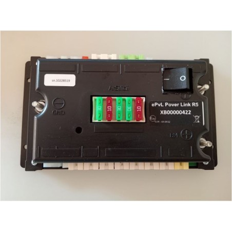
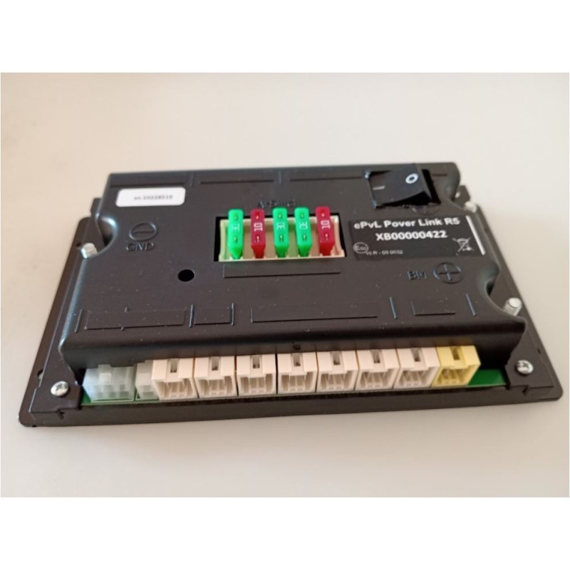
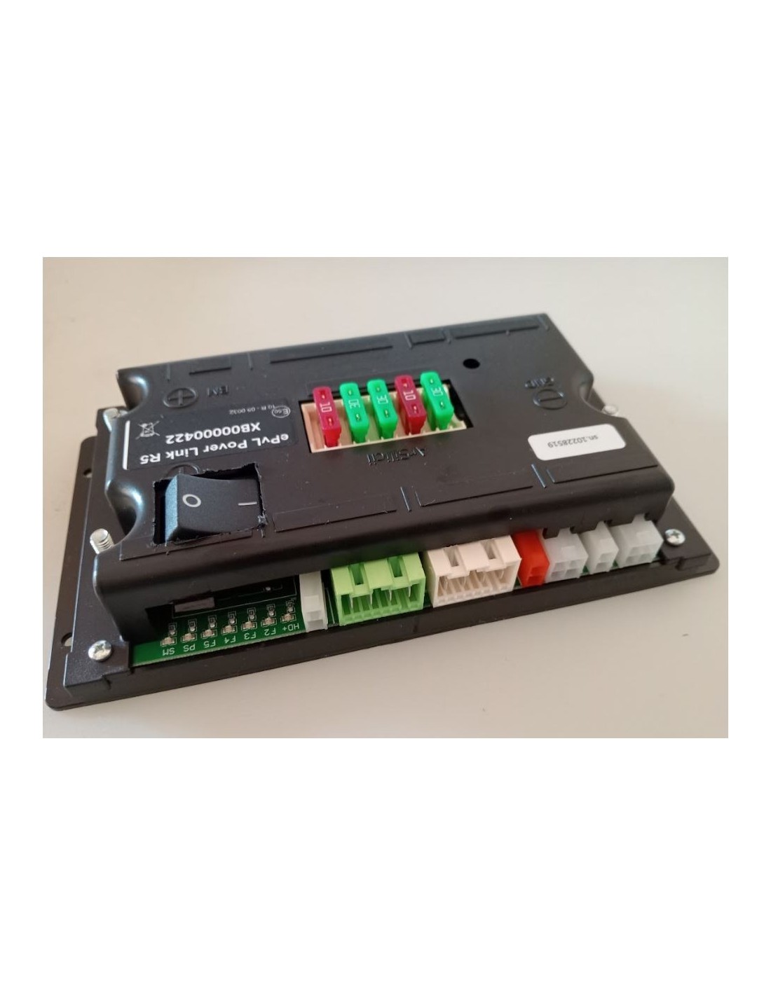
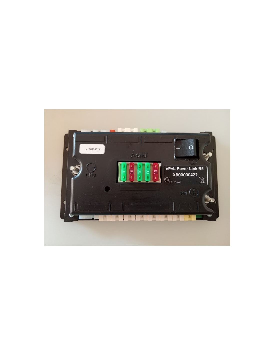
ARSILICII - NODE ePvL POVER LINK 2013/2014 - R5 FOR RAST 5 CONNECTIONS - XB00000422- RIMOR - WITH SWITCH

Mounted on RIMOR KOALA and other latest S-TTK systems (see attached manual)

ITEM MADE TO ORDER DELIVERY TIME APPROXIMATELY 10 DAYS

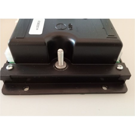
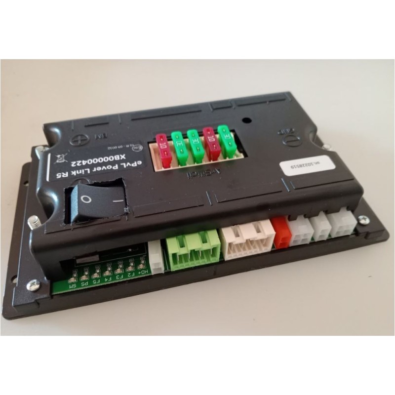
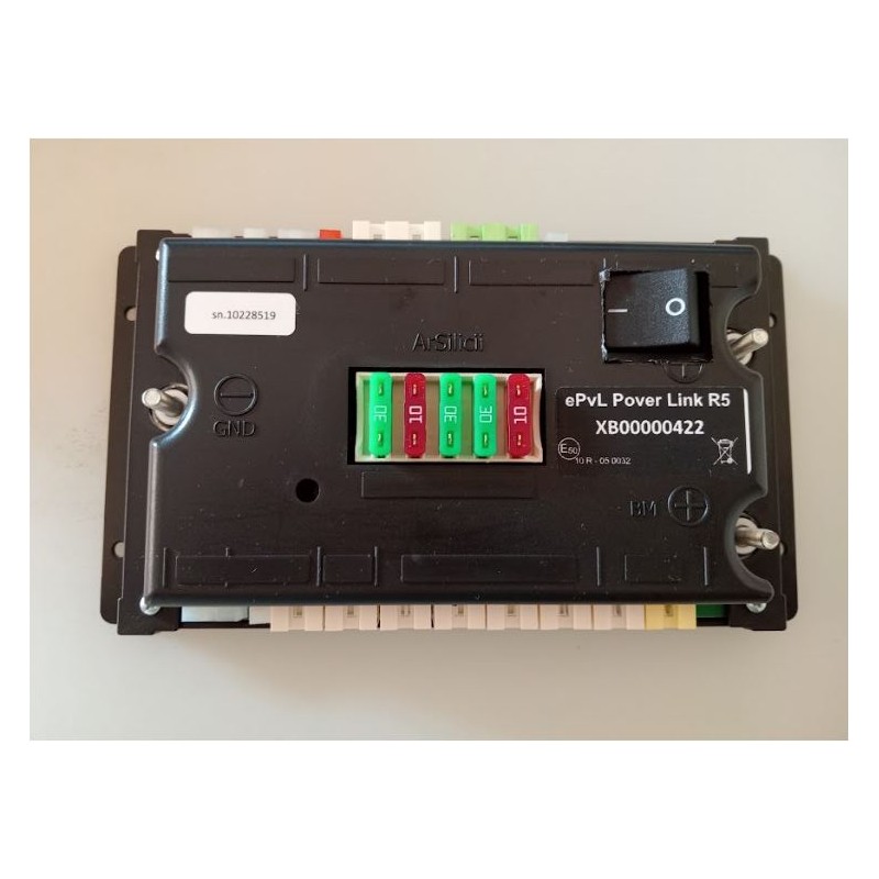
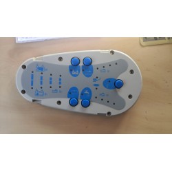
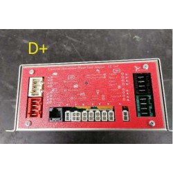
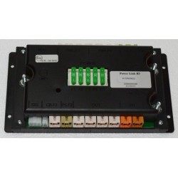
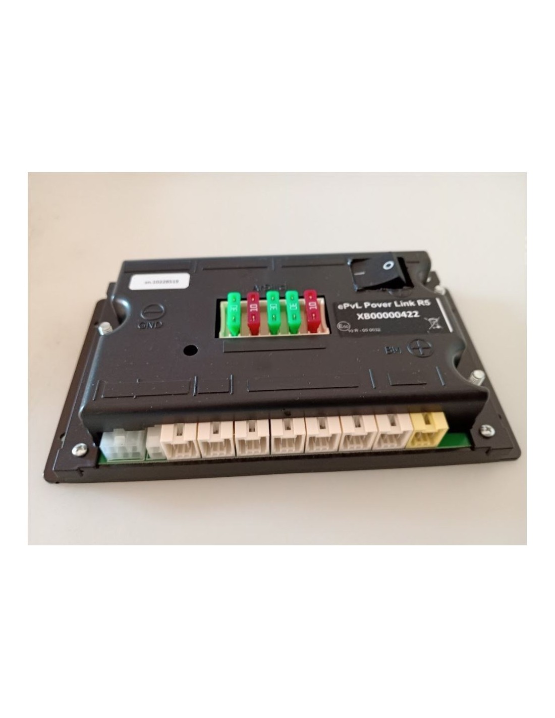
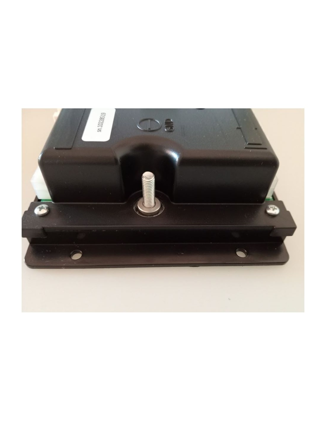
SUPERLINK power distributor

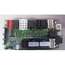
It is the device where the main energy sources converge and are distributed to the various users and to the service battery. There is also a bank of protection fuses on the board.

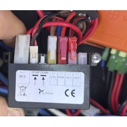
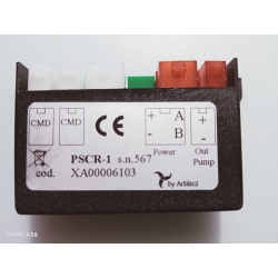
The Superlink is able to control the pump and tank levels, responding to the commands it receives from the control unit to which it is connected via the bus cable. On the top there is a status LED that provides information on the connection with the control panel. The green flashing of the LED, located on the upper part, indicates that the connection is OK, while in case of problems, the LED flashes red.

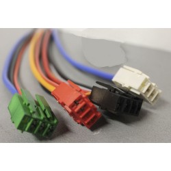
The connections of this unit are highlighted in the general system drawing at the beginning of this document.

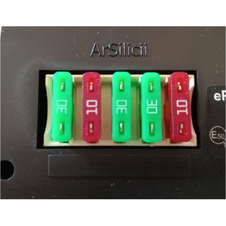
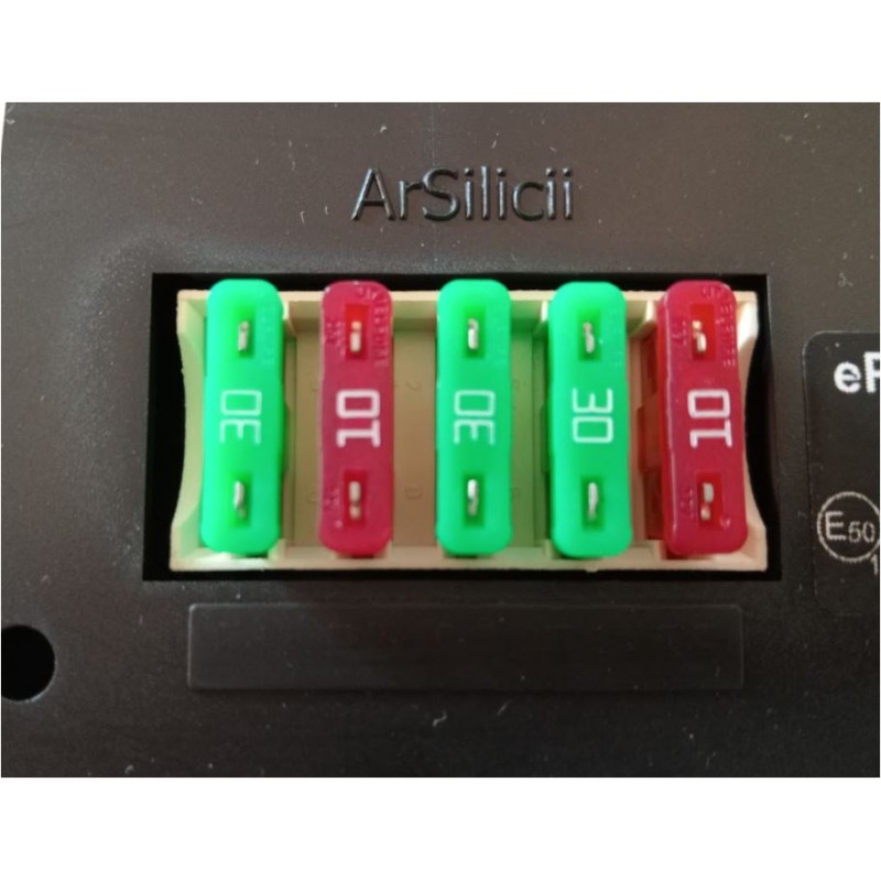
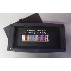
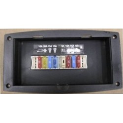
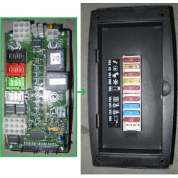
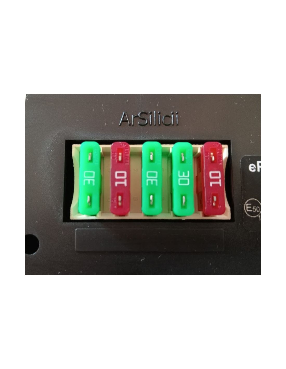
Below is a table of protection fuses.

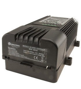
  • F1 30A BATTERY CHARGER input line protection
  • PUMP F2 10A output line protection
  • Line protection Distribution output CONTROL PANEL F3 30A
  • FRIDGE output line protection. F4 30A
  • Not Installed F5 10A

16 other products in the same category:

Customers who bought this product also bought:

Product added to wishlist
Product added to compare.

iqitcookielaw - module, put here your own cookie law text